Here is my attempt at putting the cabin top together single handed. I've lined up and screwed down and clamped the front of the four panels.
Of course, this is my Third attempt at doing this. My first Two attempts did this to my clamps. I now have steel clamps, not ^&%$^%$% plastic.
I've used good old gaffer tape to hold everything in place while I'm doing it - it's like a second pair of hands. I've put tape over the frames so that when I tab the top and sides together, it won't stick to the frames, then I plan to lift it off, de-cable tie it, fillet and glass it internally and Voila!
I've screwed blocks in place as you can see below to hold everything in position. It all lines up nicely at Frame 110 as you can see.
There is just the little matter of bending the Hoop Pine Five ply to shape, and it's tough as nails and really fights back. I carefully started adding cable ties and gently bending everything to make it fit at Frame 89, which need a lot of effort and then.....Bang!
So tomorrow I'm either going to go and get some 1/8" Hoop Pine marine ply and Laminate up the sides in place, or find some weak, flabby, soft, Gaboon, Okume or Meranti quarter inch marine ply that bends easier than the Hoop Pine.
Oh well, I guess every project has its low points..
Monday, July 27, 2009
Monday, July 20, 2009
Keel Box And Thwarts
Well, first of all.....it's light. We lifted it up just to have a look at it. One person can easily lift the bow or stern. Left chine looks pretty well edge to edge as it should be, the right not quite so good, maybe an Eight out, but it should all fair up pretty well. I guess it will be considerably heavier after we glass the hull and deck.
When I was preparing the bulkheads for the keel box sides, I glued in cleats on the bulkhead faces to hold the bottom of the sides together, since I had no good way of clamping them. Anyway, I fitted the sides so that they would just sort of slide in from the top. I also made up the thwarts out of quarter inch ply so that they were a loose fit.
We relied on the Two pieces of Two inch wide quarter ply on the bulkhead faces for our accuracy in getting everything vertical. Those strips were made up as accurately as our tools allow and they were positioned with reference to the centrelines drawn on the bulkheads when we lofted them.
..So in theory, since the bulkheads are flat, parallel, centred by laser and vertical, we should have a perpendicular keel box, I hope. Well that is the theory anyway.
We filleted and then glassed the bottom to keel side joint, checked to see that everything was glassed, no bare timber, etc, and then glued in the thwarts. They got a fillet and glass where they meet the hull. The keel box side to bulkhead joints were then filleted and glassed.
Wednesday, July 15, 2009
Stringers and Cleats
Today I trued up the centrecase, put in some stringers and a couple of cleats.
I think I'm going to go with a square section keel head, but anyway it isn't critical just yet. This morning I trued up the keel box sides and then fitted and sanded them ad infinitum to get a nice mating surface with the bottom.
That done, I started thinking how I was going to clamp everything together. It's easy to clamp at the top, but not at the bottom. I solved that problem , as well as making something to locate the thwarts when I install them by putting cleats on the back of 110 and front of 124. I did it with the keelbox sides in place and butted them right up to them, so that they "lock" the bottom of the keelbox in place. They also provide support for the Thwarts and if I've done it right, the thwarts should be flush with the bunk tops when it's all installed.
Naturally I carefully slid the keelbox sides out after clamping and before the glue set up. They got a coat of epoxy on the insides ready for glueing later. I also roughly cut out the keel hole. The Fein Multi tool cut through ply and epoxy like butter! It took about Two minutes!
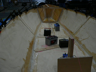
After that, I started making more stringers. I used inch and a quarter square Oregon and bevelled the edges of the exposed face a little. I guess they are heavier than beams with lightening holes, but I think they are going to be bullet proof once the cockpit floor ones are bonded to the ply. I've committed the no -no of glueing end grain, but that is really just to locate them until they are bonded to the underside of the cockpit bottom. I've put Two between 169.5 and the stern. The batteries are just to make them conform about a Sixteenth to match the curve of the hull.
I guess we will let that all set up over the weekend, then it's more woodwork for the thwarts and bunk covers. We want to use them as airtanks. I'm not sure if we will foam them or just have an inspection cover.
I've emailed Tim about the sexy curve of the cockpit sides, other guys seem to have widened the cockpit up front, but I think I like the idea of more deck to provide more reserve bouyancy in a knockdown, and will probably build it the way Chris designed it.
Monday, July 13, 2009
Grumpy Walrus
People are not made to bend double, especially older people, but Wobble was out teaching people how to sail so I had to put in another four stringers by myself.
What seems to work for me is to cut everything to plan dimensions and then get into the boat and do a bit f cutting and sanding until they fit nice. It's important to label each part "Forward", "Up" and "Left" and "Right". I almost glassed in something back to front, and my labels saved me just in time. here they are.
P.S. Before I put those stringers in, and considering I had all the frames in, I decided to lift the boat... Man! It's rigid!
Sunday, July 12, 2009
Stringers And $$$
We decided to put Two stringers towards the stern, and I needed wood for those and various cleats etc., so I set off in search of some clear Oregon....only to find none, nil, nada, zip, with the exception of some awefulold stuff. Finally I went to Lewis &Co who have been selling Oregon since 1905.
They told me that American Oregon is virtually no longer available because the logging coups were closed to protect the Spotted Owl and Bald Eagle. Canadian Oregon is supplying the European and American markets, but no one is carrying much here. I found some 30mm X 30mm. Twelve metres of it cost me $160.00. I mean, we used to burn offcuts of this stuff as kindling!! Well, so be it. I hope the Owls and Eagles are happy.
We cut out frame 89 on Thursday. We left a reinforcing bar across the middle of it which we will cut out later after everything is set up and glued. Friday we glued it in and left it all weekend to set. Monday I made up the Six stringers.
I filleted and glassed in the Two front ones, then glassed in the right side of frame 169.5. The hull should now be symmetrical. That was enough for one day. stooping in the boat glassing in stringers requires contortions.
Monday, July 6, 2009
Frames Going In..
After what seems like forever measuring that everything is flat, square, parallel, vertical, horizontal, aligned, collimated and centred, we glassed in frame 110. Then we followed today by tabbing in Frame 124 and 169.5. We knew we had 110 in OK, so we used the keel case sides as a spacer and poked and prodded until we think we got 124 right. In the picture below you can see the strap we used to get about half an inch inside the class rules maximum beam measurement.
After that we tabbed in 169.5. Now when we measured the hull using the Beckwith string system, we discovered that the Starboard side at 169.5 was about half an inch out from where it should be, most probably (fingers crossed) because of a warp in the ply or finger trouble by me.
So what we have done is glassed in the Port side and Three quarters of the bottom and its our hope that the big gap visible in the photo will close right up (fingers crossed) when we apply a little muscle and a strap.
We are getting close to ordering the rig which is most probably going to be a Two spreader Carbon layout.
Wednesday, July 1, 2009
Triangulation
Image above shows One million clamps holding their shear clamp on. There is not really much to show at the moment, but we have been busy. The centre seam and chines have been filleted and glassed. All the frames have been cut with the exception of 89 under the mast step. 18 has been glassed in as has 53 after some sistering pieces added to get a fair hull.
We fitted frames 110 and 124 and decided to sister 110 to give us a fair hull. 124 just dropped right in and fitted just fine. The sister pieces are now glued on, as are front and back 2" wide centreboard case ends. We have also laminated up the centreboard case sides so that we can use them as "spacers" when we install 110 and 124 - if all goes well, that big day will be Monday.
In all this, we are trying to follow the "measure Three Times, cut once" philosophy which is driving wobble nuts, since he can already feel the boat moving and has bought three Tonnes of Harken bling to screw on as soon as the paint is dry. Having said that we have followed Chris Beckwiths "string" measurement procedure and the boat up to frame 124 is dead square as far as we can tell. At 163, the Sides are unsymetrical by around half an inch, but we believe that its caused by variations in the plywood and will easily pull out when we drop that frame in.
Not sure if other people do this, but I found that Pythagoras comes in handy. Calculate the square root of the hypotenuse of the triangle formed by the frame number and the half beam at the deck edge of the frame, and measure and mark that amount back along the sides from the stem. If your hull is something like square, that should be pretty close to where your frame and sides should join.
We are still trying to get all our dimensions sorted out for our rig and sails. The "jib hoist" measurement is confusing since we have to create some sort of datumn for the sailmaker so that he knows where the stem fitting and deck edge are in the verticle plane.
Subscribe to:
Posts (Atom)