Sunday, October 25, 2009

It Floats. It Sails.


Yesterday morning was spent bolting on rudder fittings and a zillion other small jobs.

After lunch we put her under the crane and in she went. I550's all seem to look like they are stern heavy sitting in the water. This is not the real case, the bow just sticks up a bit.

It was blowing around 20 knots, down from the mornings 25 knots. We had the usual 1.0 to 1.5 metre Port Phillip chop.

We built in a Two degree rake on the forestay length. The boat seems perfectly balanced and the twin rudders grip well. Acceleration is phenomenal. The boat does not pound one bit provided she is sailed at around 15-20 degrees up wind, which is simply amazing.

More testing tomorrow after safety inspection.

Tuesday, October 20, 2009

Here It Is...

The last few days have been about screwing and bolting things on. Things like chain plates and forestay fitting, kite blocks, traveller ...and of course the stereo system. There is no truth in the rumour that we installed a giant sub woofer under the cockpit, we just thought that the access holes we made to get at the kite block locations would take a little speaker nicely..

Doug Prosser very kindly lifted her onto one of his many trucks with a forklift, then drove her down to RYCV.

Robert Hick is bringing down the keel today, hopefully we don't have too many problems fitting it. After much consideration we decided to lock the keel down with a single half inch bolt through the keelbox and keel and Frank Brockman made us a nice set of stainless steel bushes for the keel box sides and keel holes. We will epoxy them in. There will then be no chance of wood getting chewed away by the bolt if there is any relative movement.

We did it this way because the load paths and hardware of doing this through the keel top plate were just too complicated for me to get my brain around. The boat is lifted via Two Wichard pad eyes on the main bulkhead just eitehr side of the keelbox. We added some reinforcement to the inside of the bulkhead during the build for this. Lines also go to the kite block fittings.

Here she is....


Thursday, October 15, 2009

Flipped And Painted.

Yesterday we flipped the boat, did a little more sanding and painted the entire deck with anti skid deck paint.

Last week we also readied a cradle for her at RYVC.

Images aren't uploading at the moment...

Monday, October 12, 2009

The Great White Whale And The Theory Of Relativity


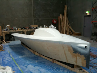
Well there she is folks - the great White Whale, not a Clownfish at all, that's where the Theory Of Relativity comes in - boats expand in size by a factor of at least Four when the time comes to sand, fair and paint them. In addition, each minor blemish stands out like, well like, choose your favourite simile.

So anyway, back to the confessional. Fairing the boat is where you pay big time and money for your youthful exuberance and lack of attention to detail in the very beginning when you built your construction cradle, cut your frames, bottom and sides, joined everything together with cable ties and started slapping on the epoxy. The main truth we learned is this: Every time in the beginning when you saw something that didn't quite line up, or wasn't exactly fair and smooth, and you said to yourself "Oh that's no problem we can fair that", you were making a mistake.

The truth is that getting it right in the beginning is much, much, easier and quicker than trying to rectify a ripple in plywood, glass and epoxy with a long board. We've done it now, and the hull looks pretty fair, flat, square, parallel, smooth, whatever, and should, we hope, look good when Robert Hicks sprays the topcoat for us. Now back to specifics.

Firstly make sure your ply is cut exactly right. Ours was as far as we can tell. There was a minor error in the plans that was detected and corrected by Tim before we got too far.

As for the building cradle, we had those Eight offsets and built a cradle with Seven supports that matched the hull profile in way of the frames as far as we could tell. I suspect that this was a mistake, and if I was doing it again, I would probably just use Three Supports, 169.5, 110 and 36, that way I should be able to see a good continuous curve on the chines.

As for joining the ply to make the bottom and sides, our joints were all too stiff, so we got a flat spot at each join that had to be filled and faired.

As for fitting the frames, we got the bottoms to fit very nicely no problems, but we couldn't get fair curves with the frames pulled in to the sides. I'm still not quite sure what was going on there. Be aware that not getting it all to fit exactly is going to give you problems at your shear line when the deck goes on, requiring a little creative freehand planing, but hey it's your project and the hull still measures OK anyway. I suspect that part of the problem was caused by the aforementioned not supporting the boat on three points. Maybe if I had, everything would have adjusted itself a little when we fitted the frames. This is something older and wiser heads can ponder.

But anyway, back to the sanding and fairing. We followed Robert Hicks advice. He is a professional yacht designer and builder, and he has built our bulb, keel and rudders for us. The recipe he gave us was as follows..

After glassing, go over the hull with a batten and fair any obvious hollows and bumps with your West system stuff. The next step is to screed the entire hull in a thin coat of West System fairing compound. I used a plasterers trowel for that. The next step is to get out the long board with 40 grit on it. Because we had relatively flat panels and frames spaced about Four feet apart at the back, I made a Twelve foot (2.4m) Two person longboard for the bottom and chines. You only need a Three foot flexible one for the sides.

Get yourself a can of spray paint in a suitably visible colour and liberally spatter dots of it over your hull. Apply the long board....After about half an hour the remaining paint will show you the low spots. If they are relatively small and shallow, fill them with "builders bog" (quick setting polyester) stop for lunch, apply a little more spray paint indicator and continue sanding with the long board. When you think you have it fair, apply your first coat of undercoat, then apply the long board, spray paint, filler and 80 grit to that. Repeat the whole process for Two weeks till you are sanding the final undercoat with 320 grit and everything is as smooth as it can get, or you just get too tired to care. Then apply topcoat.

Monday, September 21, 2009

Blinding White..

Well the filling had to stop sometime. We just got tired. So today we sprayed the deck with sandable epoxy primer. The more we put on, the better it looked.

Hopefully tomorrow, before a mid week social lunch, we will be flipping the boat.

....No videos though. I think my colleagues would agree that we don't photograph too well at our age.

Doesn't that swept back Luca Brenta lip on the cabin top look cute, as well as practical?


Friday, September 18, 2009

Mast Arrives...

Friday morning....surprise! The mast arrives. Who could resist leaving the sanding and filling and playing with toys?

C-Tech have done a great job. Everything is well designed and put together, great workmanship and....light! We asked for Two sets of spreaders, the top set just supporting the masthead when we are running with the Assymetric because Port Phillip gets quite choppy at times.

The mast comes in Two parts, joined at the hounds, which conveniently reinforces that are. I also noted that the last few inches fof the mast base are reinforced, dealing away with the engineering "Free Edge Problem" that has been the demise of more than one carbon mast. To put it another way, carbon fibre is not "Black Aluminium" and must be worked and cared for differently.

We joined the Two sections and riveted in the tee ball plates then lined up and glued the spreaders for the result below.


A word to the wise... Those beautiful spreaders are a close fit with the mast, and they need to be placed on the sections before you glue them together or you will be in a world of pain because you can't fit them later. Luckily we remembered.

We were also not thinking clearly when we ordered a carbon tang under the jib sheave box for our Two part jib halliard - the lower spreaders wouldn't fit over the tang and of course the goosneck prevented fitting from below... Doh!

Our solution after deep thought and discussion with Alex was to carefully cut off the carbon tang and smooth the area down a little so that the spreaders fitted over it. We then drilled and tapped a hole to take a small stainless steel saddle to hold the halliard (Below).


Wednesday, September 16, 2009

Persistence and Frustration.

First the persistence. We glassed the deck, then put Four inch biaxial tape over the shear line which will hopefully keep everything together if we get a "love tap" from another boat.

We are in fairing and filling mode. My back aches from the long board. It seems we have forever to go. Sanding and filling, sanding and filling. My eyes just water epoxy and my cup of tea tastes like fibreglass dust, yeccchh.


Anyway, there is sort of an outline of a boat shaped object under there somewhere.


I think the Luca Brenta style lip on the cabin top looks good, should maybe help keep water out, and be a good base for some cleats.


Now the frustration.. Delicate readers may want to shut their ears here.... C-Tech very kindly shipped our mast last Friday, right on time and when they said they would. It is now Thursday and we are still waiting for those idiots at DHL to deliver. They managed to split the Two packages and send them to different locations.

Then they tried to hide their incompetence by spouting gibberish down the phone line. Just for the record, there has not been a thing called an "import licence" for general goods into Australia since about 1968, and in any case we have a free trade agreement with New Zealand. "Delayed by Customs" sounds good until we tell them that we have already paid GST and in any case checked with Customs ourselves. "Delayed by Quarantine Inspection' was a nice try until I tell them that there is no bug on this planet that eats or makes a burrow in Carbon Fibre.

We are still waiting. On reflection it would have been cheaper if I had hopped a plane to Auckland and picked the pieces up direct from C-Tech, then flown back. It's only a Four hour trip costing less than what DHL charged C-Tech for freight, and I might well have not to have paid GST of $500 as well. Plus I could have bought a bottle of duty free Whisky for Alex at C-Tech and another one for me on the way back!

Wednesday, September 9, 2009

Now You See It, Now You Don't

That's 58 inches of C-Tech carbon prod. We put a little carbon fibre reinforcement around the receiving tube area and stem. We are setting the prod up with a single combined tackline/extender system using 6mm spectra.


We are hoping to put th e foredeck on today and perhaps finish off the fairing before glassing the deck. We hope to receive the mast some time next week. Time to get some chainplates made up....

Thursday, September 3, 2009

Progress

Just a photo of the baot with the side decks glued down and the cabin top cleaned up. We got word today that the prod is on its way from C-Tech in New Zealand and will hopefully arrive Monday so that we can fit the receiving tube and glue up the foredeck.

We looked at the prod Geometry. The photo below shows what 58" looks like. By all accounts our spinnaker is "pretty big" according to Col Anderson at Doyle sails.(Gulp)


When The Epoxy Starts Smoking...

Well we made this discovery a while ago. If you mix too much epoxy in a container it heats up. Then it gets hot, very hot. When it starts smoking it's time to carefully take the pot outside and get rid of that epoxy real quick.

Well we got the cockpit side decks glued on. If only I'd thought about the fit a little more and the placement of the weights when we held it all down I wouldn't be contemplating filling the hollows they made. Getting the shear line to look right is going to take considerable time after that little mistake.


The cabin top is glued on. We have left a "Lip" at the back to be a bit Luca Brenta-ish, and perhaps keep water out of down below a little. We will trim it back neatly when we have the time.


We made up the side decks and chain plate gussets. The gussets are placed slightly differetly according to C-Tech's instructions to match the 30 degree spreader angle of the mast. They are one inch thick laminations as per plan. We lined them up using C-Techs drawing and a string line from the notional centre of the mast. They will be glassed in with lots of biaxial tape.


We glued on our side decks and now have a definitely boat shaped object. We were (I hope!) A little more careful about that shear line.


By the way, this is the pattern for the bulb that Professional designer and boat builder Robert Hicks made for us. We weren't game to make the foils ourselves so we asked Rob to do the designing and building in that area. All are wood with carbon laminates.

Sunday, August 23, 2009

Problems Are Opportunities In Disguise.

Well we have been busy little beavers.. After the making of the cabin top - which was declared a draw between me and a sheet of hoop pine plywood, we started on the cockpit. The bunks we glassed in as bouyancy tanks. We decided that we wanted to support our plywood edges really well, so we glued 1 1/4"" Oregon onto the edges of the frames and then decided to laminate up some 1 1/2"' plywood strips to support the cockpit to deck joint. We cut out the corners of the frames, slathered everything in epoxy and then just sort of clamped the strips in place to the edges of the frames. To out complete surprise they followed something like a fair curve and were within +- 3mm or so when measured from the centreline, except in one spot where we made some saw cuts, pulled the support into line with clamps and slathered the cuts full of glue.

So we had something like a symmetric cockpit structure. We added a few more Oregon stringers to support the cockpit floor. The cockpit floor was not too hard to draft up, and we did it in Three lateral sections, from the Stern, the joints being just in front of 169 and 124. We then glued them all together on the floor, then dropped them into the cockpit when dry for some trimming. We did a similar thing to make the sides.

We decided to follow the (Pipedream? Alchemy?) construction method so we carefully taped up the frames so that nothing would stick to them and filleted and glued Four inch biaxial tape to the side to bottom joints in one continuous swoop front to back. We let that cure overnight, then screwed on some 2" x1" cross ties to keep it from "flapping", then we carefully pulled our cockpit out, turned it over, sanded and planed the inside edge to a nice round profile, then glassed that with biaxial tape as well.
On Thursday afternoon we mixed copious quantities of glue and stuck the cockpit in permanently. Today (Monday) it appears rock solid. We spent the best part of Two hours checking and planing the shearline which had a few "deviations" in it, mostly due I think to the stiffness of the ply, to get what I hope is a pleasing and regular shear. We then did the same to the cockpit to deck joints and I think they are pretty pleasingly curved as well. We cut out and glued up the side decks hopefully for fitting tomorrow.

I say "hopefully" because my fellow team member has forcefully demanded that every inch of the inside of the boat be sanded and checked by feel for those little sharp epoxy spikes that rip hands and spinnakers apart when you least expect it before the deck goes on. You can hopefully see some pleasing lines appearing in the photos below...


Monday, August 10, 2009

Slower Progress - Slaves Of The Gluing Cycle...

Progress continues, but it seems so slow as we are now slaves to the gluing cycle. There is a sequence to doing stuff that is not always apparent.

We have built the Cabin top. It has no compound curves. Hoop pine ply does not like compound curves, not like your average wishy washy Okume. Hopefuly it should not look too bad. It looks awful now since it needs to be trimmed to the deck level and sanded to an inch of its life


Much time has been spent doing what I call bracketry - supports for everything that I think needs supporting, and sufficient surface area for a strong glued joint as well. We have started on the cockpit. I cut 1 1/4" Oregon diagonally and have glued that to most of the edges of the frames that will take the bottom, sides and deck.

We stopped that process today to laminate the cockpit to deck edge supports (not sure what their nautical name would be). These are three strips of 1 1/4" plywood with the joints offset and hopefully tastefully arranged and clamped to give a pleasing curve to the cockpit edge, or at least something close to what the designer imagined.

We will take the electric plane to them tomorrow along with a tape and centreline string to see if they are anything like symmetrical. Once that is done we can build the cockpit bottom and sides. We plan to fillet and glass the bottom to the sides in place and then lift them out to tape the inside edges before reinstalling. That cockpit floor to cockpit side joint is going to take a lot of punishment, especially if you weigh as much as I do.

We are in the process of ordering a C-Tech (NZ) carbon rig, but with Two sets of spreaders - the uppers just supporting the masthead when the kite is up. Port Phillip is a pretty choppy place and has 15 -25 knot sea breezes in summer, so we really have to think about that masthead whipping around. The sales are Doyle Fraser Laminates that should be matched pretty well to the rig as Doyle are apparently across the road from C-Tech.

Robert Hicks has done a beautiful keel, bulb and set of rudders for us, I will post photos as soon as I can.


Monday, July 27, 2009

The Cabin Top Saga...

Here is my attempt at putting the cabin top together single handed. I've lined up and screwed down and clamped the front of the four panels.

Of course, this is my Third attempt at doing this. My first Two attempts did this to my clamps. I now have steel clamps, not ^&%$^%$% plastic.


I've used good old gaffer tape to hold everything in place while I'm doing it - it's like a second pair of hands. I've put tape over the frames so that when I tab the top and sides together, it won't stick to the frames, then I plan to lift it off, de-cable tie it, fillet and glass it internally and Voila!

I've screwed blocks in place as you can see below to hold everything in position. It all lines up nicely at Frame 110 as you can see.


There is just the little matter of bending the Hoop Pine Five ply to shape, and it's tough as nails and really fights back. I carefully started adding cable ties and gently bending everything to make it fit at Frame 89, which need a lot of effort and then.....Bang!


So tomorrow I'm either going to go and get some 1/8" Hoop Pine marine ply and Laminate up the sides in place, or find some weak, flabby, soft, Gaboon, Okume or Meranti quarter inch marine ply that bends easier than the Hoop Pine.

Oh well, I guess every project has its low points..

Monday, July 20, 2009

Keel Box And Thwarts

Well, first of all.....it's light. We lifted it up just to have a look at it. One person can easily lift the bow or stern. Left chine looks pretty well edge to edge as it should be, the right not quite so good, maybe an Eight out, but it should all fair up pretty well. I guess it will be considerably heavier after we glass the hull and deck.


When I was preparing the bulkheads for the keel box sides, I glued in cleats on the bulkhead faces to hold the bottom of the sides together, since I had no good way of clamping them. Anyway, I fitted the sides so that they would just sort of slide in from the top. I also made up the thwarts out of quarter inch ply so that they were a loose fit.

We relied on the Two pieces of Two inch wide quarter ply on the bulkhead faces for our accuracy in getting everything vertical. Those strips were made up as accurately as our tools allow and they were positioned with reference to the centrelines drawn on the bulkheads when we lofted them.

..So in theory, since the bulkheads are flat, parallel, centred by laser and vertical, we should have a perpendicular keel box, I hope. Well that is the theory anyway.

We filleted and then glassed the bottom to keel side joint, checked to see that everything was glassed, no bare timber, etc, and then glued in the thwarts. They got a fillet and glass where they meet the hull. The keel box side to bulkhead joints were then filleted and glassed.

Wednesday, July 15, 2009

Stringers and Cleats

Today I trued up the centrecase, put in some stringers and a couple of cleats.

I think I'm going to go with a square section keel head, but anyway it isn't critical just yet. This morning I trued up the keel box sides and then fitted and sanded them ad infinitum to get a nice mating surface with the bottom.

That done, I started thinking how I was going to clamp everything together. It's easy to clamp at the top, but not at the bottom. I solved that problem , as well as making something to locate the thwarts when I install them by putting cleats on the back of 110 and front of 124. I did it with the keelbox sides in place and butted them right up to them, so that they "lock" the bottom of the keelbox in place. They also provide support for the Thwarts and if I've done it right, the thwarts should be flush with the bunk tops when it's all installed.

Naturally I carefully slid the keelbox sides out after clamping and before the glue set up. They got a coat of epoxy on the insides ready for glueing later. I also roughly cut out the keel hole. The Fein Multi tool cut through ply and epoxy like butter! It took about Two minutes!


After that, I started making more stringers. I used inch and a quarter square Oregon and bevelled the edges of the exposed face a little. I guess they are heavier than beams with lightening holes, but I think they are going to be bullet proof once the cockpit floor ones are bonded to the ply. I've committed the no -no of glueing end grain, but that is really just to locate them until they are bonded to the underside of the cockpit bottom. I've put Two between 169.5 and the stern. The batteries are just to make them conform about a Sixteenth to match the curve of the hull.


I guess we will let that all set up over the weekend, then it's more woodwork for the thwarts and bunk covers. We want to use them as airtanks. I'm not sure if we will foam them or just have an inspection cover.

I've emailed Tim about the sexy curve of the cockpit sides, other guys seem to have widened the cockpit up front, but I think I like the idea of more deck to provide more reserve bouyancy in a knockdown, and will probably build it the way Chris designed it.

Monday, July 13, 2009

Grumpy Walrus

People are not made to bend double, especially older people, but Wobble was out teaching people how to sail so I had to put in another four stringers by myself.

What seems to work for me is to cut everything to plan dimensions and then get into the boat and do a bit f cutting and sanding until they fit nice. It's important to label each part "Forward", "Up" and "Left" and "Right". I almost glassed in something back to front, and my labels saved me just in time. here they are.


P.S. Before I put those stringers in, and considering I had all the frames in, I decided to lift the boat... Man! It's rigid!